Building The Engine House
Designing and Building the First Structure for the Layout
Its been a reasonable amount of time since I worked on the layout, long enough to restore the creative juices, so I decided to start a new project, the Engine House.
This is a nice little project, not as much of a job as the freight house will be, so I figured it would be a realistic one to take on right now, plus I wanted to get something new added to the layout before the Doubleheaders Layout Tour, which was on Saturday (yesterday).
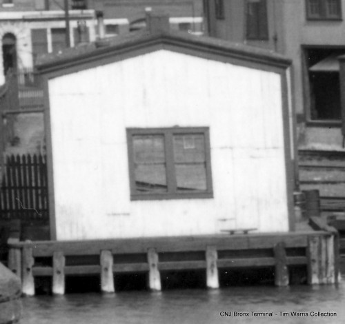
The engine house at the terminal was an interesting structure as there wasn’t enough space to cram it into the yard, so it was built hanging over the Harlem River.
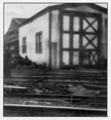
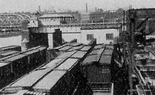
In my collection of images, I only have 3 that show the engine house, which was torn down in the early 50’s. Fortunately there was enough information on those 3 images to complete the design.
A good shot of the rear of the building, sitting on piles over the river.
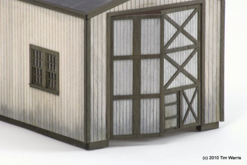
This is a great, and rare, shot showing the front of the structure, scanned from a 1928 issue of Railway Engineering magazine. The mis-matched doors are an interesting detail, no idea why they were this way. I am assuming that is a man door on the right hand door, at least, that is what I put in my version. Either this shot, or the one before it, is a bit distorted. In this image the building looks quite tall, the other, it is almost square. I had to play with the proportions a bit to get what I thought was the right compromise. Thank goodness for parametrically driven, 3D solid modeling software…
Another grainy scan from an old magazine article from the 1920’s. This is a good side view of the structure. Not much detail can be seen from it.
After playing for a while I settled on a structure that was 43′ long x 24′ wide x 19′ high. Seemed to look right.
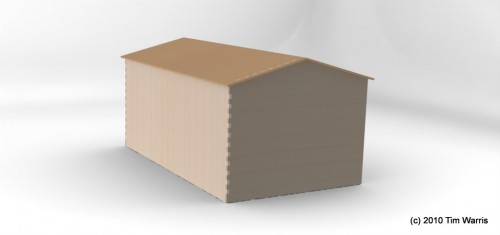
Since this building will be entirely laser cut, I had to do a through design in CAD first. I prefer to do all design work in full 3D even though it takes significantly longer than if I just did it in 2D. The advantage of 3D design is that it does allow for a clearer idea of what the final design will look like. And if designed properly, assigning the right relationships to dimensions, changes can be made downstream that will allow the entire design to be updated with a simple input of a number. For example, after the complete design was done, I wanted the building to be 2 scale feet higher, all it takes is changing the height dimension and the entire model updates. Sounds simple, but it takes years of working with the software to get to that point.
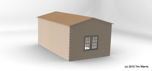
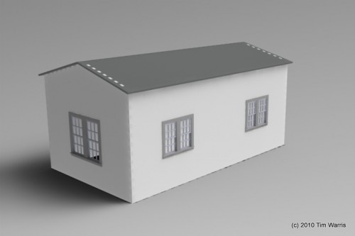
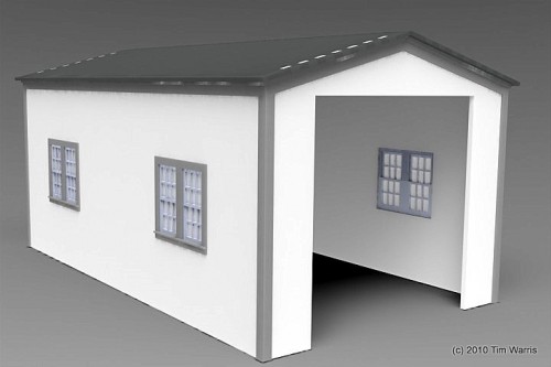
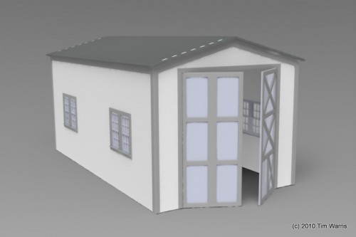
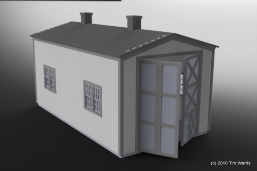
Test renderings of the building as I progressed through the design process. I worked on this off and on for about 3 days. Probably 10-12 hours of design time into it.
I did a screen capture of some of the process, adding trim to the model. Its very thrilling to watch….
I had the design complete and prepared all the necessary files for the laser cutter late Thursday evening. While cutting it all out, I decided to video some of it. Its very thrilling to watch….
With the parts all cut out, that left me one day to get the structure built if I wanted to be able to add it to the layout before the tour.
Building The Model
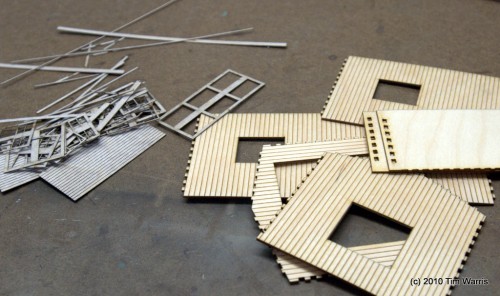
Friday morning, parts in a pile. I’ll I have to do is arrange them into the shape of an engine house.
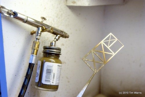
First up, painting all the parts. I airbrushed all the trim with what looks like Rail Brown if I read the label in the picture correctly.
Windows all painted, trim next.
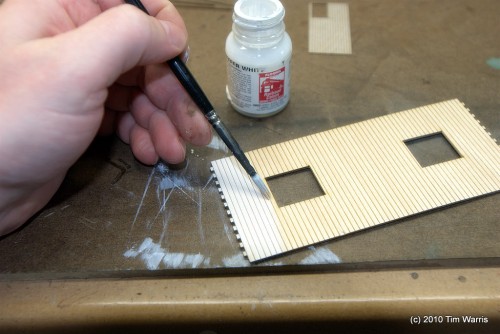
All the walls given a light coat of white.
The trim is a nice contrast on the white back.
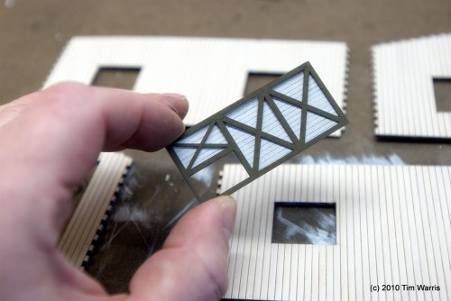
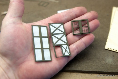
Doors built up, and one window. The windows are made from 5 separate pieces. I like the freedom of being able to design the windows needed for a specific structure, but find the process of building them very tedious!
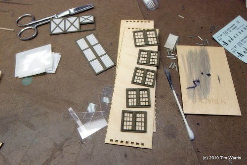
All five windows built up. Five seems to be about my limit for window building in a single sitting! Don’t know how I’m going to make it through that freight house project with all its windows and doors….
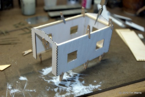
Main structure built up with some re-enforcing inside to keep it all flat and straight. The walls are all tabbed to allow it to fit together tightly.
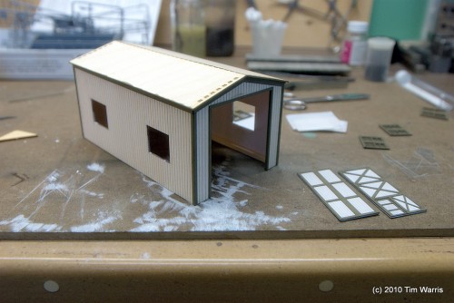
Trim added, roof in place. Just need to add the doors and windows. About 5 hours into the build at this point.
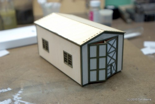
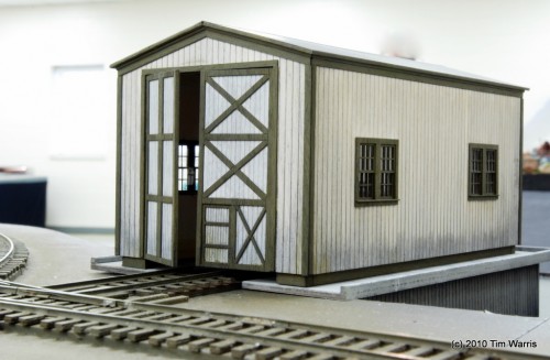
Windows and doors in. I played with the idea of making the doors open and close but decided to just glue them in place for now. If I make them open and close, I would need to add interior details and there wasn’t enough time for that. Perhaps later.
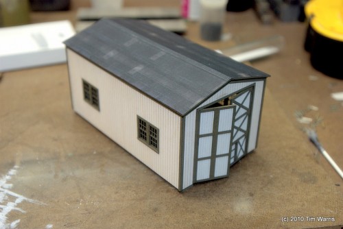
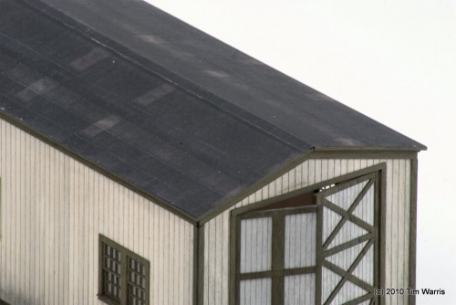
Roofing material added. This is the first time I tried using printed roofing, and I think it looks pretty good. It was self adhesive, which made this step go very fast. 5 minutes instead of the tedious half a day it usually takes, and looks far better. There was quite a sheen on the material, so I have it a shot of Dullcote, which knocked that down nicely.
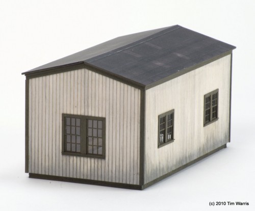
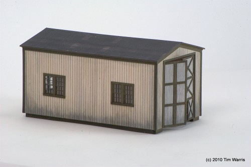
Some final weathering added to the structure and it is mostly complete! I say mostly because there are still some details missing such as the chimneys and the base with piles that the structure sat on over the river.
The weathering was done using leather dye diluted with alcohol. I coated the side of the wall with pure alcohol first then added the mixture to the bottom of the walls allowing it to wick up into the wet surface. This simulates staining near the bottom of the walls nicely.
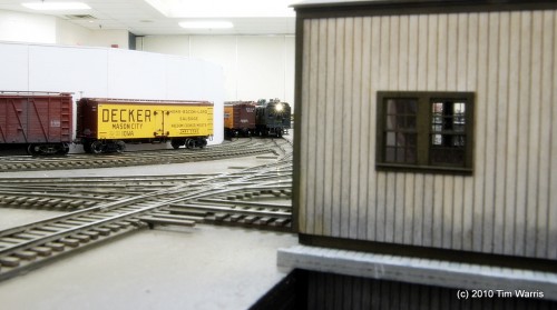
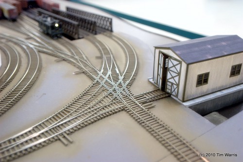
Sitting in place on the layout. Fits right in nicely!
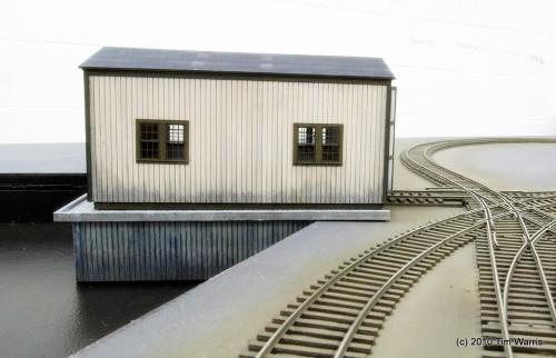
I made a quick base for it to sit on, but this will be changed to piles later.
I often hear from modelers how great it must be to have a laser cutter, and well, it is! However, it doesn’t make the process of building models any faster, in fact it is much, much slower. To design a structure, with all the nuances of design, it takes a LOT of time. Far more than most people imagine. The advantage of the laser is that the parts produced, once the design is complete and tested and tested and tested, are very precise and go together easily. The finished models always look pretty good, if the design is done correctly. But it is by no means an easier or quicker way to get a model, just more precise.
I did manage to get the model built in time, finishing around 4 in the afternoon. The layout was loaded into the van and around 9 I built the temporary base for it to sit on.
The model reeked of paint all during the layout tour.
About the Author:
I'm your host, Tim Warris, a product developer in Port Dover, Ontario. Since March of 2007 I have been documenting the construction of the former CNJ Bronx Terminal in HO scale. For my day job, I design track building tools for Fast Tracks, a small company I own and operate. Fast Tracks makes it fast and easy to hand lay your own trackwork. Stop by our website to learn more!
Posted by: Tim | 03-28-2010 | 01:03 PM
Posted in: Engine House | Latest Posts



Tim
It WAS interesting to watch the laser cutting video and the CAD drawing show! What program do you use for the CAD work? One can see that the preperation time is what makes the extar fine details possible. the ability to make the detailed drawings from the photos is the true artisty.
Looking forward to seeing the video of the next project. One big question comes to mind. Is it a simple process to scale up (or down) the drawings to say O (or N) scale and then feed them to the laser? Also a video of the window assembly process would be a good one to include in the next chapter.
Again, thanks for the insperation and explanation of your processes in building the super layout.
Jim
Fantastic. I enjoyed the laser cutter video. It’s amazing the fine detail it is able to achieve on those windows. How does machine know which cuts to make first? Does the software figure it out on its own or does the user have to program the order in which the cuts take place. I remember using old school CAD machines in shop class (about 20 years ago) and programming individual lines of numerical code so that the lathe or milling machine knew where to cut, when to cut and to what depth. Very tedious and boring work and if you screwed up, it could be disastrous! However, the end result was almost always worth the effort… most of the time. 😉
Hi,
Scaling up or down to other scales is possible, but it can also be a lot of work. The laser beam has a width, and this has to be taken into consideration when designing parts that interconnect, otherwise the fits will be sloppy and inaccurate. The better designed laser cut structures will compensate for this in the design, the lazy designers will just accept this slop.
To scale to a different scale, that “offset” for the width of the beam will also scale, and become too large or too small, so the fits have to be reworked to compensate for that. Believe it or not, that is a very time consuming process. So while, yes it is technically possible to scale, it is only a starting point.
The laser figures out what to cut in what order, and it is usually a source of entertainment to watch, because it seems to have a short memory, missing parts and running back to get them after…
It can be controlled somewhat in the CAD work.
Bravo on the engine house – it looks great!
Tim
I should have asked if the CAD software you use is just for the laser unit you have or is it something generic that anyone could buy. The drawings you get are super and the software seems that it could be used by anyone buliding from scratch or a measured drawing or photo.
Jim
Simply wonderful!!
That is a great video.
Any chance this building will become a kit?
It is a nice size engine house or car barn.
Tim,
Engine house looks great. Glad to see you posting again.
Tim,
Well, you did it again with not only a great video but a great project as well. It simply must be fun to do what you do. Of course, only a business could afford software and hardware like this. I tried pricing the same and it’s out of my league. Thanks for your time and effort. Thoroughly enjoyed it. More please!
George
Tim,
Very nice work as usual. Two thoughts:
The door on the left looks more like it would be foldable. I’d hazard to guess whether the folding door replace the more ornate door on the right or vice versa, but damage to engine house doors often had only one half of the set replaced.
Also, for another source for your Bronx Terminal track layout, see Railroad Construction: Theory and Practice (1917) by Walter Loring Webb, available on Google Books. The plan (p 409 actual) illustrates curve radii and track spacing, as well as that for the transfer bridge (16′ 9″). [A little late?]
Ben
Hey Tim,
I’d be interested to see how you finalise the set of points out the front of that wonderful looking loco shed. Any possibility you can record that process in a video?
Tim;
I stopped by the booth at the National Train Show today. The layout and the new engine house looked great!
Looked busy when we were there, and the person we drove up with wanted to get back on the road about 3:00, otherwise I would have made another pass around the show and possibly had a chance to stop and talk.
I followed the construction of the Bronx Terminal on-line and found it fascinating.
Just was wondering what was up lately as there had not been a posting in a while. I really admire the work you have done on the Bronx Terminal. Having built a number of Fastracks turnouts and involved with lots more on our club layout here in Sarasota FL that your product is great and I look forward to seeing more of your work. Scott Hurley
Is the CAD program that you are using Solid Works? Also what make of laser are you using?
Thanks for posting and keep up the great work.
Duncan
Yes, this was done using SolidWorks. The laser is a Universal M-300 35 watt laser.
Interesting work here. The great thing is to see that effort that would normally go to the cutting process are transferred to the design process. A great way to improve model building. I’ve been using CAD software to design my scratchbuilding projects in the last 2 years with great results, but teaming that with a laser cutter is fantastic. Fantastic in way, because it isn’t a way to kill creativity but to further it.
In the last photo, we see the track in close up. What is the thin material you use as roadbed? Couldn’t find any clue through your entire blog.
Matt
I don’t understand how the engine house track works.
The roadbed was cut from 2mm plywood. Laser cut….
Removable rails were used to drive OVER the turnouts in front of the engine house. A unique solution to a lack of space. A good explanation of the process can be found on Phil Goldstein’s site at this link…
http://members.trainweb.com/bedt/indloco/crrnjbxt.html#Trackage
Hi Tim,
Its been a real pleasure watch this recreation of time’s past, come to life. I keep coming back. The craftmenship is unbelieviable and very award winning. I like watching the video of the laser cutter. Wish I had one of those. It would be a lot easier building this unique roundhouse where, I do volunteer work.
Great work! Keep it up and look forward to seeing more.
Looks like your doing a great job. Trying to copy the details from thoughs picturs must be a challenge
I just found your site. The engine house is a fine model. Having your own laser cutter is definitely a plus as it allows you to create custom structures. I model in N-Scale and create custom buildings using a CAD program and then printing on paper and gluing on thin plywood. Not bad but the holes for windows are hard to do.
I am also wondering how you will place track to the shed through the switch points. Hope to see a picture of your solution soon.
Great model.
Don
Hi Tim,
regarding the different doors I think it was necessary to construct the left door as a folding door for allowing enough clearence to the outer ferry track when doors are open.
Nice shed,
Michael