Tidal Adjustment
Waterboard for Bronx Terminal
When I designed and built the benchwork for the terminal I made a slight miscalculation on the water level. I took a guess at the distance from the ground level and the water level, and I got it wrong by about 3/4″. The water ended up being too low.
After doing a bit of research about tides along the Harlem River and reading a few articles on float bridges I confirmed that what I built would be okay as there could be quite a difference between the level of the float and the level of the ground, depending on tidal changes and the load on the floats. This difference was taken up by the float bridge, a pivoting bridge connection between carfloats and terra firma. Sometimes the float bridge could be an incline, sometimes it could be level or a decline. What I am aiming for is either level, or a slight decline. The water level as it currently is would result in a very noticeable decline, and while technically correct, I thought that would be a bit distracting.
This error was apparent shortly after I set the first carfloat on the water section and I have been debating on how to fix the issue for some time. I decided to have a new piece of plywood cut to fit precisely over the original water section. I also decided that since I am designing a new piece I might as well make it wider so it could accommodate two carfloats sitting side by side, a scenario I have seen in many photographs. Having two float moored together at the float bridge would provide storage for 34 cars! And look good too…
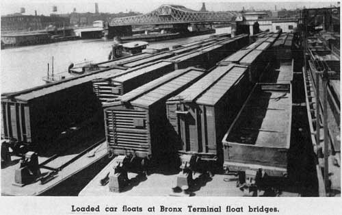
Using two floats means I could simply swap them to generate a fresh set of cars for the terminal.
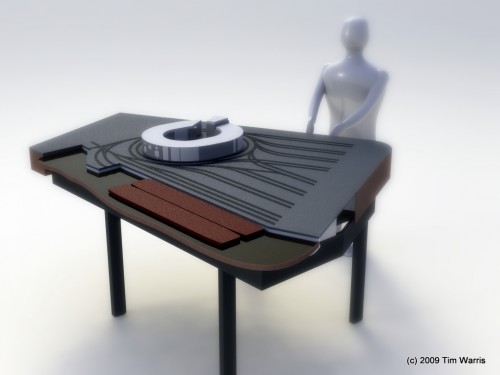
Having designed the entire layout in 3D CAD means that I could return to the original files to extract the necessary information to have a new piece of plywood cut. Theoretically it would be a perfect match. I created a simple 3D model of the carfloats and inserted them into the design to confirm they would fit well. I wanted to have a couple of inches of modeled water around the floats, and also create a wavy edge to the layout at the water. In photographs I didn’t want to have straight edges at the water, they stand out too much.
Virtual model of the Bronx Terminal.
Once I had the design finalized I sent the files to Brian, my friend with the CNC router who cut out all the parts for the layout two years ago. I went over this afternoon and we cut out the new section. I should have brought the video camera, it is very cool to watch.
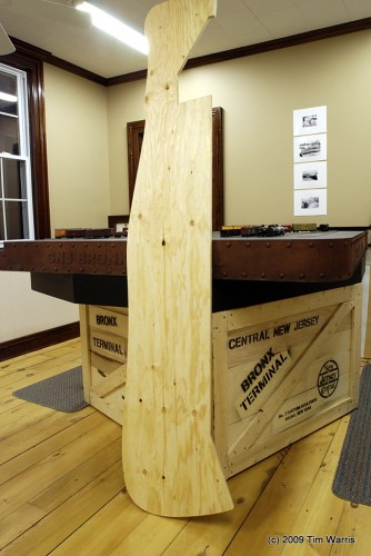
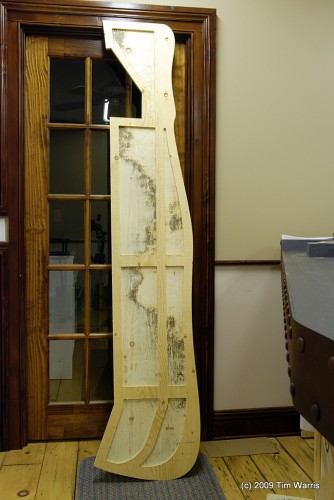
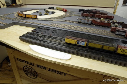
This is the new piece, cut from a single sheet of 5/8″ sheething. To keep it as light as possible, I created pockets in the bottom to remove as much material as possible.
This is where having the entire layout designed in 3D really pays off. I was able to keep the pockets precisely where they should be by designing the part virturally in place on the layout. The CNC router simply follows the lines I drew.
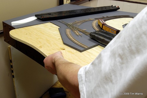
Of course the other advantage of having designed the layout in 3D is that it fits together like a puzzle.
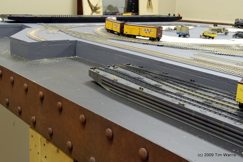
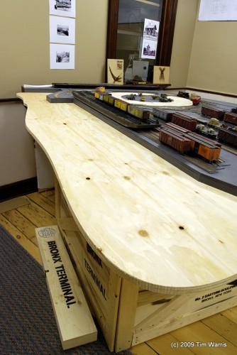
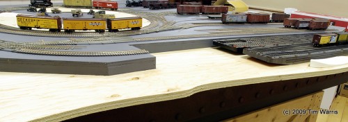
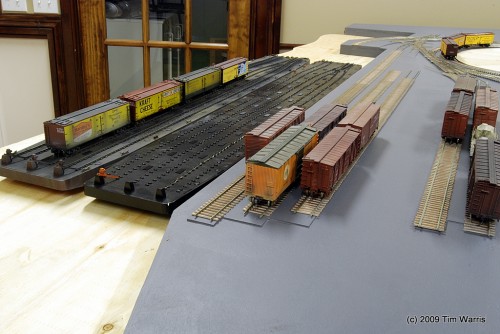
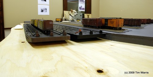
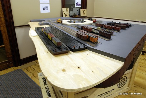
It fit perfectly, added some more space for the second float and brings the water level up so the float bridge will only have a slight decline grade on it.
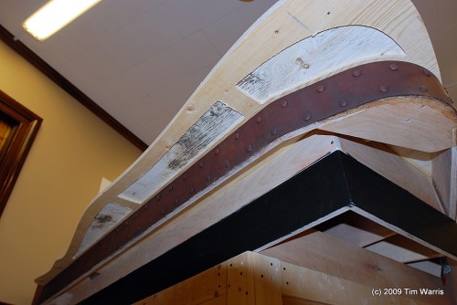
The pockets line up precisely with the original edge of the layout. The other pockets will be hidden under the new “waterboard”.
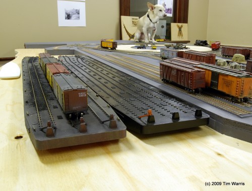
The float bridge will occupy the space between the track and the carfloat.
Two floats side by side. The hull of a steam tug sitting next to the float. I am not sure where I will put the tug yet, but I do want to incorporate a tugboat into the layout.
This should look great!
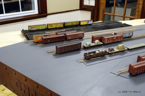
Ignore the boxcar missing a set of trucks….
Will look better once there is actually some water modeled, but so far I am happy with the addition. Adds about 6″ to the width of the layout, but that isn’t an issue.
-T.
On to Next Section…
About the Author:
I'm your host, Tim Warris, a product developer in Port Dover, Ontario. Since March of 2007 I have been documenting the construction of the former CNJ Bronx Terminal in HO scale. For my day job, I design track building tools for Fast Tracks, a small company I own and operate. Fast Tracks makes it fast and easy to hand lay your own trackwork. Stop by our website to learn more!
Posted by: Tim | 03-08-2009 | 10:03 PM
Posted in: Benchwork Construction | Latest Posts

Hi Tim,
Isn’t it amazing how layouts have a tendency to “grow”? Sure wish I had access to a CNC router…
Wait until I add water….
-T.
I like that it covers over the rusted layout fascia – visually providing a more flowing transition to imaginary space. Nice solution.
Are you going to soften/round off the water edge?
Whatever you use for water would need to be flexible.
Also, if you do any light breeze wave chop action – pay attention to leeward shadows – (still spots) caused by land and water obstructions. It’s a great level of detail those of us who sail/live near the water appreciate.
Trying to figure out why the dimple/protrusion of water just fore of the tug…
Hi Chris,
Thanks for the feedback. The hiding of the rusted fascia was an accident, but I agree, it does add an interesting element to the layout.
Not sure how I will finish the edge of the water. I could add a thin band of rusted material like shown on the rendering in the post. Or I might paint it to match the water therefore hiding it a bit. Had not thought about rounding it over, that might hide the edge of the water as well. Have to think about it.
Good tip about the waves. From the experiences working with Envirotex for water (which I intend on using) I will be lucky to get any waves at all. Not sure how others have done it, but I have never been able to get ripples in Envirotex.
-T.
Things are really coming together Tim. It looks great!
Ken Patterson – (the guy who does the outdoor module photo shots for various major manufacturers) had an article on “Modeling Large Bodies of Water” using a sponge glazing technique with a modeling paste. The end result can be seen here:
https://www.walthers.com/page/ir12full.pdf
(Walthers catalog link)
Tried to find the article in Model Railroader, but can’t put my finger on it immediately.
I believe it’s in Railroading Along the Waterfront which also has an article by John Pryke.
i guess with the CNC router the waterboard was not considered torture? dick cheney approved i assume