Mind The Gap
All Gaps Cut
I am 98.675% confident I got them all….
With the NMRA Train Show rapidly approaching, I am focusing hard on getting this damn thing running. Reaching that goal will take a lot of work over the next weeks. This week, I am spending most of my time working on the layout, and so far I am making pretty good progress.
It took two full days to cut all the rail isolation gaps in all the trackwork. I worked very slowly and carefully being careful not to damage any of the trackwork and also to be certain I didn’t miss any. Missing one would be very not good. Some of the gaps can not be cut after the track is installed as they have to be done using a jewelers saw due to the tight clearances involved. Most of my time was spent studying the individual track pieces and determining where to make the cuts.
After the gaps were cut, they sections were tested with a continuity checker to make sure there were no shorts or missing gaps.
The job wasn’t as bad as I thought it would be. Until this stage in construction I could not cut any of the gaps as it makes the track sections weak, and I needed to handle them quite a bit, so I delayed the job until the last possible minute. This meant spending 2 years thinking about it and answering the question, “how you going to wire that thing?”.
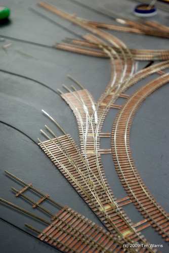
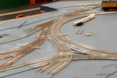
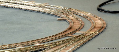
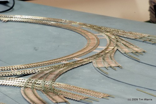
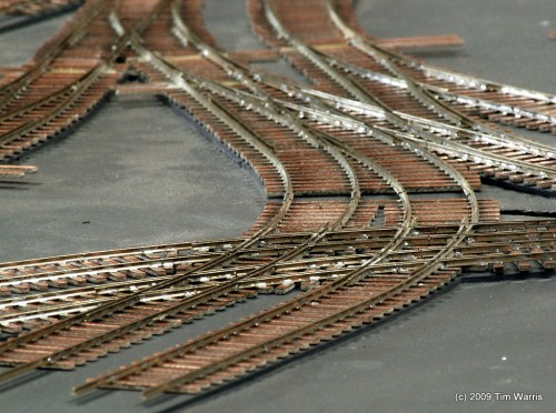
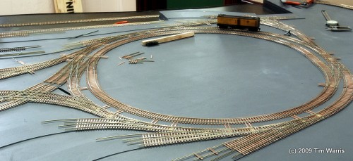
Today, I fit all the sections together and soldered them into a single piece. All the missing PC board ties have been added in. It is now, finally, all sitting in place. This was another job I have been thinking about for two years!
It all went together well, fitting very precisely and seems to run smoothly when I push a car or two through it. Until the switch machines are installed, its very difficult to tell how well it will actually run as the switch points don’t yet seat precisely, need the switch machines to hold them tight in place.
I still have another piece of trackwork to make, one final turnout. I will make that one up tomorrow and install it into the rest of the trackwork. Other than the straight yard tracks, its the trackwork construction is pretty much complete.
Will have to make up a “Golden PC Board Tie” and have a little ceremony with some local dignitaries for the last solder. There will be speeches and polite applause.
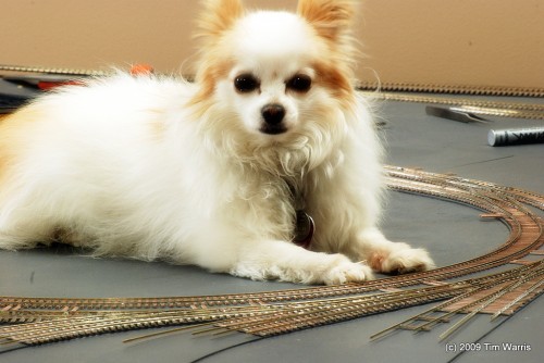
A local dignitary inspecting some trackwork. He barked in lieu of applause.
-T.
On to Next Section…
About the Author:
I'm your host, Tim Warris, a product developer in Port Dover, Ontario. Since March of 2007 I have been documenting the construction of the former CNJ Bronx Terminal in HO scale. For my day job, I design track building tools for Fast Tracks, a small company I own and operate. Fast Tracks makes it fast and easy to hand lay your own trackwork. Stop by our website to learn more!
Posted by: Tim | 05-13-2009 | 08:05 PM
Posted in: Cutting Gaps | Latest Posts | Track Construction
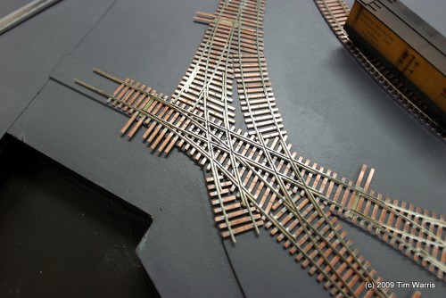
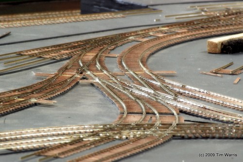
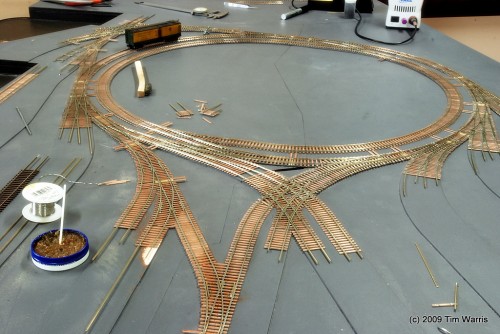

I am making an assumption that there will be an extension on the top of piece number1 that will allow the interchange track to move cars beyond the switch at the top. It looks like there might be a very tight area to get the locomotive and a car on that part of the track. Be sure to post Golden spike (tie) event vedio.
Jim, the short lead turnout in the top photo is the lead to the engine shed. Tim has posted in the past about how the tracks crossed over the other turnout, by a vertical removable section of rail. Tim has some idea as to how he is going to handle that section of track, I suspect it won’t be used all that often anyway. In real life, I am sure it was fraught with difficulties, and not something that would “normally” have been done…but then A4 switches arn’t normal either.
James Powell
Jim Powell
NO I was refering to the lead which is crossed by that track. That is the interchange lead.
Jim Evans
Jim Evans, from the track arangements it is my assumption that the pice you are refering to is the track that goes to the “other yard” that Tim is not modelling, the two yards are joined at this location via tracks that went under the bridge.
The leads for all the other tracks are the outer tracks of the two circles. Unless of course we are looking at different things 😀
Tim,
Those track photos are things of beauty! Congradulations on a job well done. Can we expect one of your usual great videos of a boxcab running a boxcar or two around the thing soon? Even if you just clipped the leads to a track temporarily, it would be fantastic to see the operation of all this complex track.
Congrats on another milestone, it’s a big job
Hi Jim,
Ian is correct, the little spur shown at the top of the layout when to “The New Yard”, a short extension and yard added in 1929. I will be adding a short lead here to allow the carfloat to be unloaded.
I do plan on modeling this section as well, once the “Old Yard” is completed.
Sorely missing from this site is a decent bio of the terminal…