Boxcar Carbox


I finished off the CarCarriers last night with a bit of stenciling on the lids. I used some of the same stencils I had left over from stenciling the crate that the layout sits on.
They are now full of cars, 35 in total, ready to make the trip to Spingfield this weekend!
-T.
Re-Post
I made a post a some time back about cutting the necessary electrical isolation gaps for the complex trackwork in the terminal. Over time it has gotten buried in the posts and since it is a question that comes up quite often I thought I would re-post it here. I have also created a category on the right hand side of the site called “Cutting Gaps” that will keep this post easily accessible.
The gaps in the PC board ties were all cut with a triangle file. The gaps in the rails are all cut using a jewelers saw. Using a jewelers saw allows the blade to be removed from the saw and slipped between the ties and then re-attached to the saw. The rail is then carefully sliced using a fine blade. This leaves a very thin gap that is almost invisible. Since the rail is soldered to all PC board ties, there is no chance (OK, little chance) that the gaps will ever be able to close up, so no filler is necessary.

Gapping complex trackwork.
The number one thing I get asked about when someone sees this trackwork is “how will you wire this?”. Seeing all those frogs it looks very complex but once you understand the basics of where to isolate sections of track you develop an eye for where to cut the gaps.

I design a lot of complex trackwork and part of the design is determining where modelers will need to cut gaps to have the trackwork operate properly. DC or DCC, the gapping is the same when building ultra-reliable track. To have trackwork (turnouts and crossings) work without shorts or equipment stalling it is necessary to “cut the frogs out”, that is to completely isolate the frog from the rest of the turnout and feed power to the frog independently from the turnout. Power is supplied to the frog from either a switch machines contacts or from a ground throw that has contacts on it.
The link will show a animated rendering showing how this works….
Rendering illustrating switching power to a frog.
The “polarity” of the frog is set to match either the “north” or “south” rail depending on which way the turnout is set. The same is true for multi frog trackwork. Each location where two rails cross each other (frogs) will need to be isolated from the rest of the track and powered independently based on the route selected.
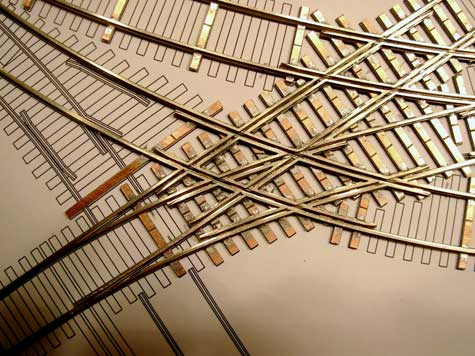
Image Copyright (c) 2007 Tim Warris

What I have illustrated here is all the different frogs in the first section of trackwork I built. The gaps cut through the rails are shown in red. After studying the drawing for a while and thinking how a train would run through the trackwork I determined where each frog would have to be cut using a jewelers saw. (Link to article on this technique)
Power will be fed to each frog from the contacts of switch machines relative to the route selected. Additional contacts will be needed and will be supplied from relays connected to the switch machine contacts.
It isn’t as difficult as it appears, but when complete there will be lots of wires feeding all the different frogs, which does make it appear complex, but in reality it is the same circuit repeated several times. You end up with stuff like this…

But it runs 100% reliably!
-Tim
Gap Update
Oops.

A sharp eyed modeler pointed out a mistake in the gapping in the section shown above. The Blue/Pink/Green frogs can all be a single section, like in the image below….

The logic being that only a single train can travel over the entire pink section at a time, therefore it isn’t necessary to isolate the three frogs, it can be left as a single section.
Thanks to David at The Gauge for pointing this out. It will save a few wires!
-Tim
Finally Finalized
This is the second part to this post. To see the series in order, click the link and follow the “On to Next Section…” links to get back here.
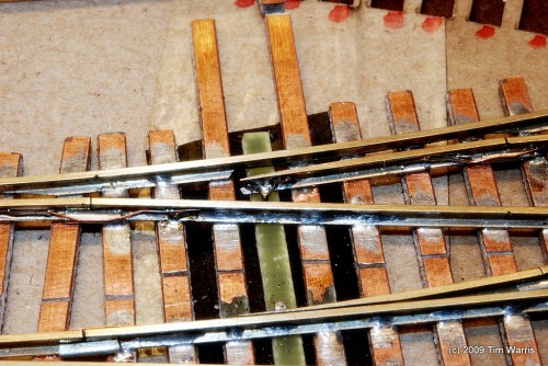
A few days ago (OK, 6 weeks) I started working on the throwbars for the turnouts. I have been playing with a few ideas on how to make them pivot as freely as possible considering the very short length of some of the switch points. Some will be less than 1″ long!
I decided to use a technique I developed several years ago and wrote about in one of our Fast Tracks Newsletters. This method uses a spike soldered to the switch point inserted into a hole in a PC board throwbar tie that has had the copper foil removed.
The advantage of this method is that there is no solid joint between the throwbars and the switch point, the only connection is between the switch point and the spike soldered to it. The spike is free to pivot int he throwbar. On most normal turnouts, this isn’t an issue as the solder joint is strong enough to overcome the stresses on it, but with very short points this will not work.

For all the tests I had just been removing the copper from the PC boards with a file, but that is a pain in the fingers. I decided to get some etchant (ferric chloride) and etch the PC board ties to remove all the copper foil. This will leave me with a supply of nice throwbar material.
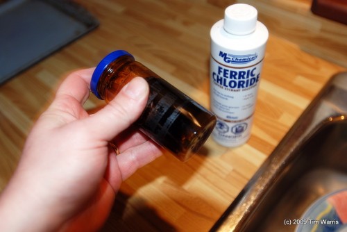
About 50 ties were placed into a glass jar with the etchant. Shaking it speeds up the process.
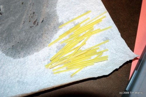
Ferric chloride is very aggressive, this only took a few minutes. This stuff is nasty, so I chose not to drink it.
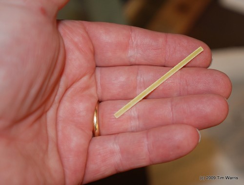
The result is a nice material suitable for a throwbar.
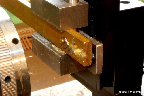
The key to success with this technique is to have holes drilled in the throwbar that are as square to the points as possible. This will eliminate any stress on the solder joints.
To achieve this I made a crude but effective jig in my lathe to hold the throwbar square to the drill.
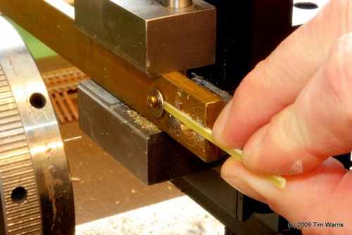
The throwbar is simply slid into the groove in the jig and held in place by hand while the holes are drilled. First, the holes are located with a centre drill, then drilled through with a small bit.
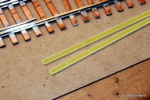
The results are holes that are accurately spaced, and square to the surface. The distance between the holes is .465″, which opens up the points a bit more than normal. Any less and the wheels will catch the open point of these very small radius curved turnouts.
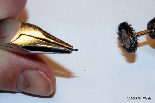
Next I prepared a spike. To solder to a Micro Engineering (30-106) spike the blackening HAS to be removed. Solder will not stick properly to blackened surfaces. I use a wire wheel in my Dremel tool to quickly remove the blackening from the spike. This works very well and leaves a nicely polished surface suitable for soldering.
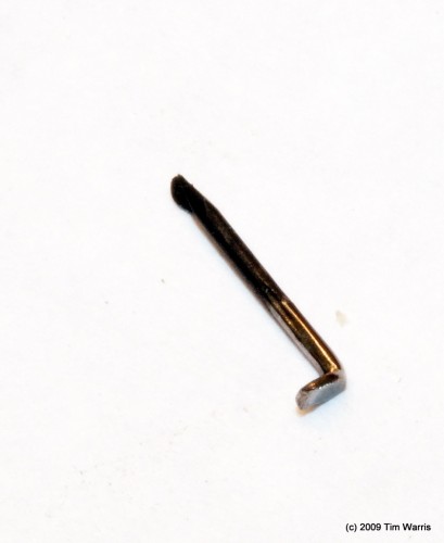
Only the top of the spike needs to have the blackening removed, the rest of the spike will be trimmed flush with the bottom of the throwbar tie.
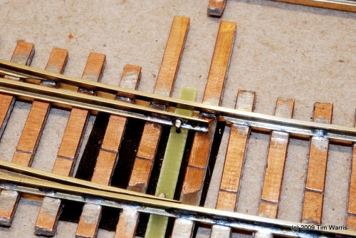
The spike is inserted into the hole in the throwbar and trimmed flush with the bottom of the throwbar, then removed.
The throwbar is then put into position between the head ties, the spike re-inserted down into the hole and soldered in place to the switch point. It is easy to adjust and position the throwbar by remelting the solder joint and siding the throwbar into position.
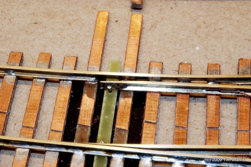
Once complete, the throwbar moves very freely with the switch points pivoting at the spikes and rail joiners.

Small wire jumpers are added between the closure rails and the switch points to feed power to the points reliably.
This seems to work very well and I will proceed with this technique for the rest of the turnouts on the layout. I like this method, and believe it will be reliable as there is very little stress on the solder joints, the main purpose of the solder joint is to pull the points back open, when closing the points the pressure should be on the spike itself pressing against the switch point. With minimal clearance in the holes in the throwbar there is little to no twisting being applied to the solder joint. Thats the theory anyway, it is still untested under any kind of use.
Three down, 24 to go…
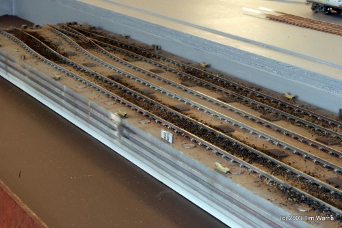
and for no reason at all, a picture of the carfloat.
-T.
On to Next Section..


