Engine House Lead
Click any of the images to see a larger version.

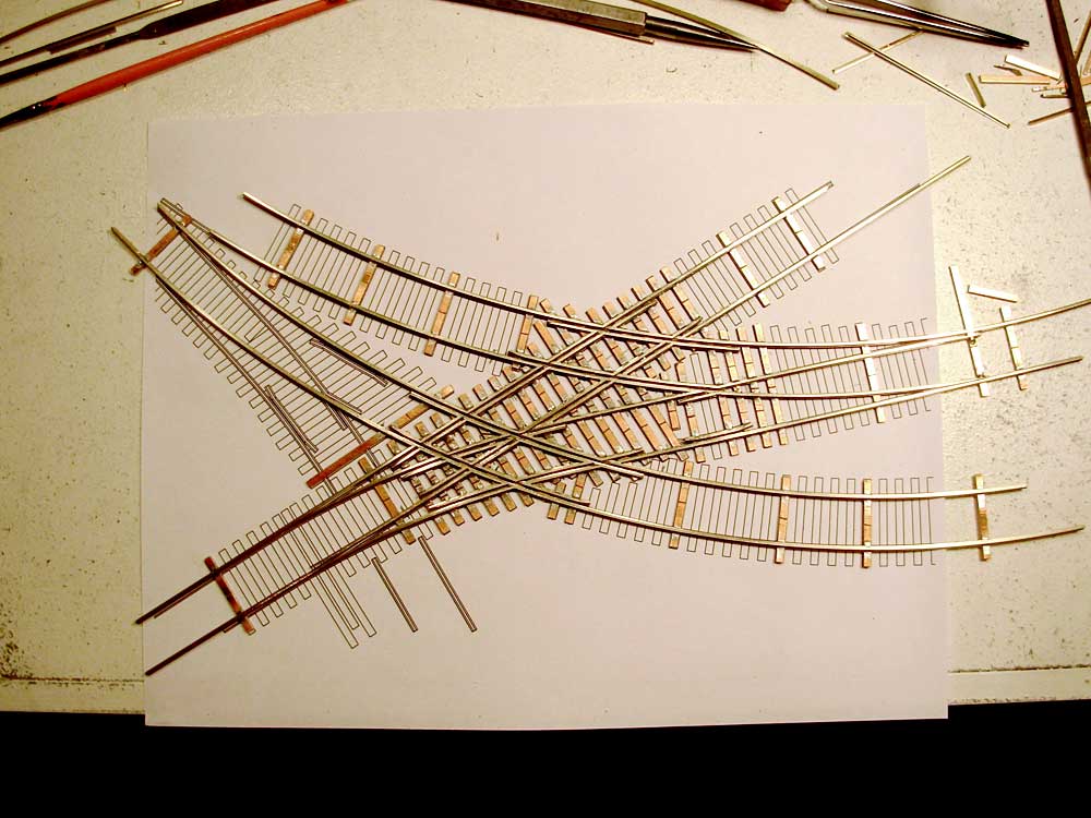
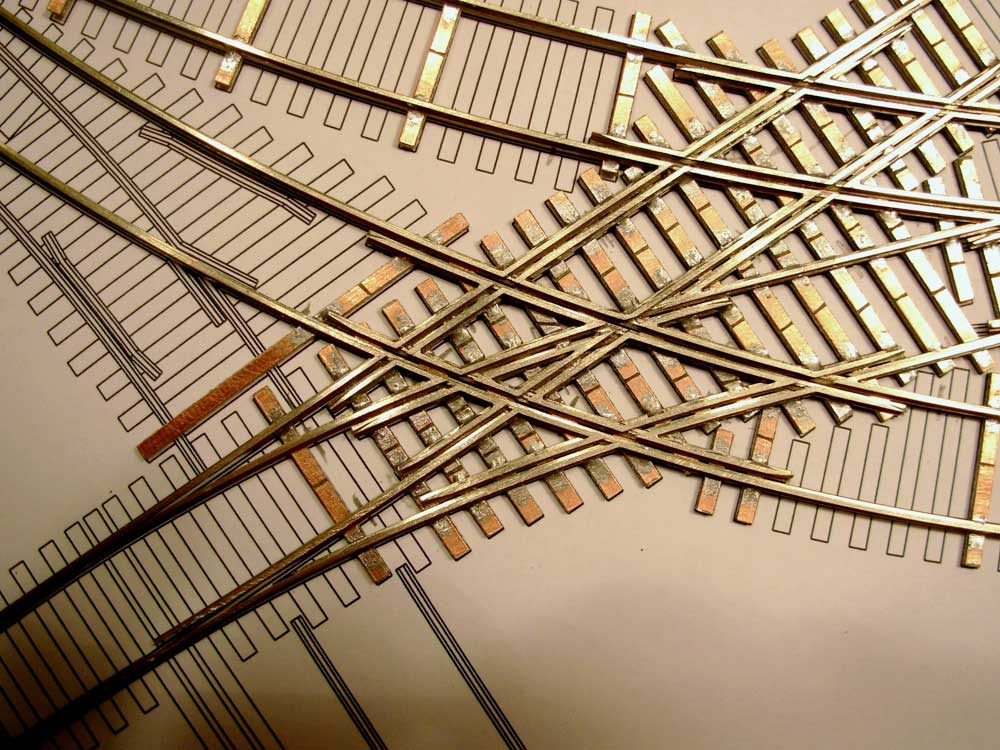
With the uber-complex triple turnout complete, I move onto the next section of trackwork, the two curved turnouts leading into the engine house. From these turnouts the engine crawled (literally) over other turnouts into the engine house by means of temporary rails placed on top of the trackwork.
I will attempt to model this feature using a small piece of larger rail notched out to fit in place, but have not yet tried to see if this will work. If I can’t get it to work I will simply leave it off.
While it isn’t as cool as the first piece, it isn’t without its charm. The first turnout is both straight and curved in that it starts to curve after the switch points. The second turnout is a curved wye, and is about a #2 with the right hand route ending where the removable rails would be placed to cross over the other trackwork.

These are some tight curves! About 14 1/2″. The equipment that was run here, and that I will be using will all be able to handle these.


Since the closure rails are so short on a turnout as small as these I will likely cut them off and hinge them when I install the trackwork in place, but for now I have them soldered to the throwbars.
This section was joined onto the first piece with rail joiners to keep everything aligned.
On to Next Section
-Tim
Building the Bronx.
Finally.
Four years ago I sold a locomotive I no longer wanted, and with the extra cash I decided to buy something I normally wouldn’t. I went down to the local hobby shop and bought a book that caught my eye, “Where the Rails Meet the Sea”. Mainly due to a picture of a very interesting freight terminal that was once in New York.
The more I studied it the more intrigued I became with it (ok, maybe obsessed). The complex trackwork was hard to believe! An entire rail yard, freight house, car ferry and engine house in about 1 acre.
I had to build it. Fortunately for me online there was a pretty good track diagram of it, but little else. I studied the track plan for quite some time and decided to re-draw it accurately in CAD.

Building the trackwork would be an extremely difficult task. Possible, but likely well beyond my skills. For a while I had been tossing around the idea of making a fixture to assemble turnouts at the workbench, and thought this approach might work well for something like this.
I spent a bit of time contemplating how to make a fixture and worked out some of the details to manufacture a prototype. I did a few test tries on some scrap wood.
The initial tests worked quite well, and I built a few #6 turnouts with it. I was quite impressed myself, and decided to use the fixture to build turnouts for my Port Kelsey which I was just getting started on. Well to make a long story short, a few people spotted the fixtures and wanted one for themselves. Ron, my brother also saw an opportunity with them and offered to bring them to market online. And Fast Tracks was born.
Four years has gone by and still no Bronx Terminal. Until now.
I don’t have much in the way of an overall image of the terminal. I do have one, but it is packed in a box somewhere as I still haven’t unpacked all my model railroad stuff after our latest move. Once I locate it I will post it on the site. For now, you will have to refer to the track plan. Tonight I completed the first piece of the Bronx puzzle, the triple lapped turnouts at the engine house end of the facility. This is on the lower left hand side of the drawing. The three lapped turnouts are the most complex portion of the trackwork, and I should have started with something simpler, but I was looking for a challenge.
Update – Image found

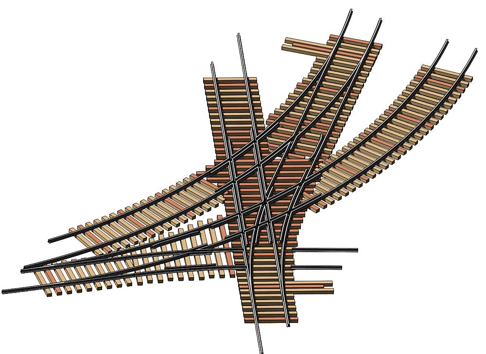
Below is a 3D model I made of the portion of track I started with…

Image Copyright (c) 2007 Tim Warris
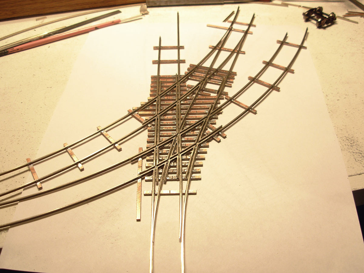
and the completed trackwork…

Image Copyright (c) 2007 Tim Warris
Here is a shot of the real thing.

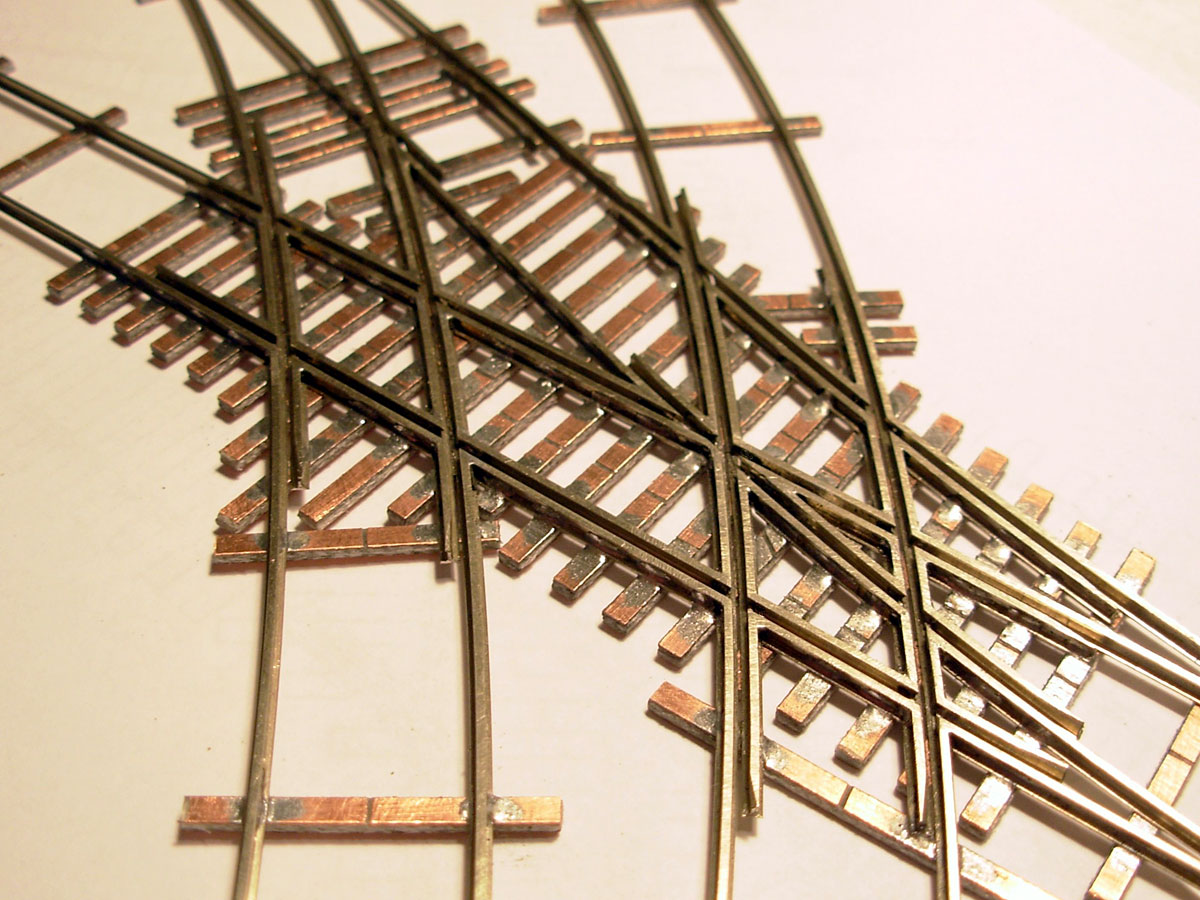
If you look closely at the image above two rails can be seen protruding from the right side of the lower turnout. These rails led into the engine house and never actually crossed through the turnout, they crossed over it. To get to the engine house the crew had to lay steel rail across the top of the turnout, and drive over it! I am not making this up, they actually did this for decades. If you look close, a support can be seen in the middle of the turnout for the rails. The portable rails can be seen on the lower right side of the image.
If you look closely at the lower left front of the engine in the large version of this picture below (click on the picture) the engine is sitting on these pieces of rail on top of the turnout.


Image Copyright (c) 2007 Tim Warris
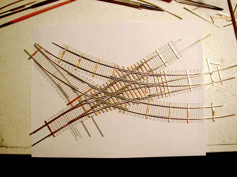
Image Copyright (c) 2007 Tim Warris

Image Copyright (c) 2007 Tim Warris
Here is a short video showing a set of wheels rolling through the complex trackwork. It operates extremely smooth, I am very excited with how it turned out and am looking forward to the next piece of the Bronx puzzle. Click on the right facing black arrow to start the video.
On to Next Section
Update – Nov. 25, 2008
Construction Posts Index
Since there are lots of posts on this blog that are not necessarily related to the building of the CNJ Bronx Terminal, relevant posts about just construction can be tricky to follow.
To help make it easier to follow along with the building of the layout, I have added a “Next Section” link to the end of each post that deals with the build. Simply click on that link to move onto the next post. You can follow these all the way to the most recent relevant post.
I have broken down the posts into the following categories, in order from the beginning to the most recent: